

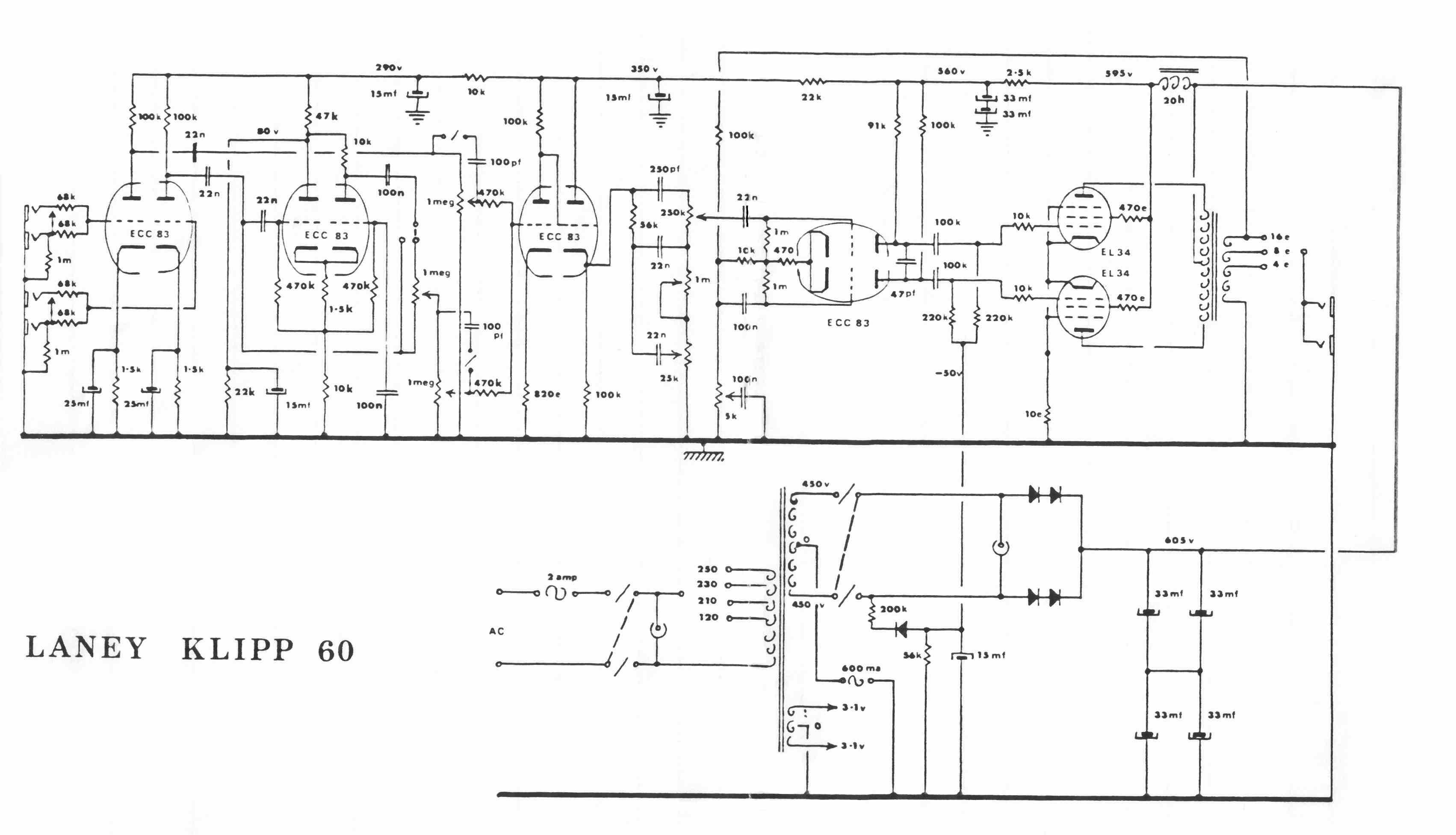
aliparla escribió:Cuidado Pablo, que en ese esquema que has puesto hay una errata: son 1,5 k pero se ha borrado el punto de en medio, por eso están tan separados el 1 y el 5. En este otro se ve bien (lo pongo en enlace porque es muy tocho):
http://www.prowessamplifiers.com/schema ... ipp_60.jpg
Curiosamente, poniendo 1k5 pitaba mucho, por eso puse el trimmer, pero al subirlo a 15k dejada de pitar (más que dejar, creo recordar que subía la frecuencia y dejaba de oirse). Ahora no me acuerdo de mucho, en cuanto tenga un poco menos de trabajo me refresco la memoria y me meto al lío
Hay que trabajar en ese circuito con los cátodos, esas dos resistencias son las que habría que ajustar (poniendo dos potes por ejemplo) para conseguir una recta de carga igual a la que pone en el enlace Gordillo, que viene todo explicado de p.m. :
http://stevepedwards.com/OldValveAmpPos ... dy-part-1/
Tirad por los esquemas originales de laney, porque los voltajes los teneis bien, y debería de sonar la cosa.
La resi de 120k, así como R38 y R39, yo creo que deberíais de sacarlas.
Y cierto , debe ser 1k5:
Stage 2 pre amp
For the second valve – triodes 3 and 4 that will have an amplified signal (about 6V max) input from triodes 1 and 2, there is a different gain design for each triode:
This seems a form of asymmetrical Long Tail Pair, with only 80V at the anode of triode3 because of the 22k and 47k voltage divider splitting the 300V HT between them, but not quite proportionally because each triode is asymmetrical in parallel also. Triode 3 has a 47k load and triode 4 has a 47k+10k = 57k load.
If you wanted to work it out roughly, use the spec sheet value for the EEC83 figures for each anode plate resistance:
Typical
characteristic:
Ua = 250 V
Ug = -2 V
Ia = 1,2 mA
S = 1,6 mA/V
Ri = 62,5 k?
??= 100
This would give a triode 3 resistance chain of 62.5k + 1.5k + 10k = 87.5k
This would give a triode 4 resistance chain of 10k + 62.5k + 1.5k + 10k = 97.5k
The total valve resistance is roughly 1/87.5k + 1/ 97.5k = 1/R = 1/0.00001577. R = 46k.
This value is in parallel with the 22k, so these give a resistance of about 1/22k + 1/46k = 15k
Simplified, this gives:
This is in series with the 47k triode3 load, so the proportional voltage for this divider chain is 46k/15k = 3.1:1 or 300V/ 3.1 = 95V or so. The measured schematic value is 80V at the anode as written.
Close enough to see how that divider works.
Ok, the other major design difference here I haven’t seen before is that this stage only amplifies the output for triode2 (blue). Triode 1 bypasses it completely (red) and goes straight to valve 3, triode 5.
Triode 4 grid is fixed to 0V ground via the 100nF cap to pin 7. This is the fixed reference for the LTP at this valve (orange line). Remember, an LTP amplifies the difference between both grids.
The gains and clipped stage plots for this valve2 may be something like those below once the calculations are done for each triode load resistor.
The schematic value is 80V so maybe I’ll just work out the quiescent values for this triode3.
The resistance of the triodes 3 and 4 in parallel similarly worked out as above.
Plate resistances and 10k load in parallel = 1/62.5k + (1/72.5k) = 33564 ohm.
This is in series with the 11.5k cathode resistance = 45k ohm
Total quiescent valve current = 80V/45k = 1.7mA
11.5k cathode resistance x 1.7mA = 20.4V cathode voltage.
20.4V/6.6 ratio = 3.1V bias across the 1k5
Well even if the bias point of -3.1V is wrong, it seems if you want distortion, you will get it here no matter what the bias is, as there would be no cathode current at all for any grid signal above 1.5Vpp, and there may be up to 6Vpp from the first pre amp because of the up to 60 gain from valve1.
A change of 1V grid voltage gives a change of anode load voltage of about 70-35V= 35V so a gain of about 35V/1V = 35. This signal gain at triode3 is superimposed at the load resistor of triode4 so a load line for that triode could be drawn also, but it is still at around 1.7mA but with a slightly lower HT due to the drop across the 10k load, so little point. You get the general idea hopefully.
Now it seems you can have the output from triode 2 AND/OR triode 4 passed on AND mixed with the output of triode 1 at the grid of triode 5 depending on the position of the switch KlippSW. I think this is the “Klipp” switch that gives the full distortion tone, but will have to check the wiring to mark the panel. Both red and blue paths seem to have optional 100pF bright caps switches also, as there are 5 switches on my unmarked panel. 1 mains, 1 standby, Klipp switch and so I guess, these 2 tone switches – 1 in the Normal section and 1 in the Klipp section. This implies that one knob in the Klipp section may be a 1M pot “mix” control between clean (blue) and distorted Klipp (blue) signals, and the other a volume/mix pot to triode5 for that blue mix with the red clean channel.
The 3rd pot is another volume/mix pot for the clean red channel and triode5 volume which must be pot 5 on the panel and pot 1 is the 5k NFB presence pot at valve 4 LTP cathode.


